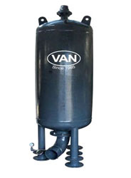
BLADDER VESSELS
WATER HAMMER CONTROL DEVICE

The outflow from the Bladder Vessel is throttled to some extent . The outflow line consists of a non return valve. The return flow back in to Bladder vessel is appropriately throttled by the smaller size by pass line, which is provided with a control valve to adjust the throttling as per site requirement..In this manner continuous deceleration occurs by returning water column and y by air cushion.
The vessel is made out of high tensile carbon steel and is manufactured to rigid quality standards, as burst vessels containing air are more dangerous than those containing only liquid. The Bladder is sandwiched between top and bottom flanges as shown in the catalogue. Entrapped air from the Bladder will be removed by the air valve located at the top flange.
For special application where it is essential to allow air entry in to pipeline, we can provide arrangement, such that, the Bladder vessel forces water and then the air to contain oscillation of water columns.
The Bladder is coated with food grade Butyl rubber for normal water application. For sewage water we can supply Bladders coated with Nitrile rubber. For petroleum products the pre charge will be of Nitrogen and Bladder will be coated with nitrile rubber.
We can design optimum size of the Bladder vessel for a particular site by using simplified monographs presented by D.Stephenson, F.ASCE
-
Features :
- Available in 6,10,16,20 and 40 Bar working pressure
- Sizes from 8 to 10,000 liters
- Larger inlet size to water chamber as per water hammer analysis.
- Min vessel thickness in 6 mm, inclusive of 2 mm corrosion allowance.
- Water does not come in contact with vessel.
- Full size floating Bladder reinforced with high strength nylon, coated with food grade impervious Butyle rubber for long life.
- Drain arrangement to check pre charge air pressure
- Optional, protection cover, and base frame
- Indigenous tailor made designs. Easy availability of products and spares.
-
Application :
- For water hammer control. The Bladder vessel inlet should be connected to main line as near to non return valve as possible. In any case the distance should not exceed 5*D (D=Dia of NRV)
- If the pipe lines are long, one can install NRV at intermediate location. Bladder vessel can be installed after the NRV.
- The return wave water column forces water through by pass line at very high velocity, and this velocity is killed instantly in the large volume of the Bladder vessel, and will release dissolved air. The air escapes through air valve provided on the top of the vessel
- The Bladder vessels control the pressure wave shocks created by sudden stoppage of pumps due to power failure, or sudden stoppage of valves, or sudden starting of pumps.
- Special design are available for sewage water containing fibrous material.
- Small units are available for arresting water hammer shocks and unwanted noise in Domestic pumping systems.
| Sr.No. | Description | Air Vessels | Bladder Vessels |
|---|---|---|---|
| 1 | Vessel Volume | 300% | 100% |
| 2 | Air Compressor, and Control System | ||
| 3 | Dead water in vessel | ||
| 4 | Location | Nr Electric supply | Any where |
| 5 | Can in be used for air induction on negative pressure, in pipe line? | ||
| 6 | Air and water surfaces in contact? | ||
| 7 | Space / Cost |
OPERATION
The pre charge pressure in the Bladder Vessel. Air Chamber 8, is kept lower than the lowest pressure in the pipe line as per analysis. When the vessel is connected to pipe line, the air in chamber & gets compressed and becomes equal to line pressure. Upon failure of electricity, negative pressure starts at connecting pipe 10, and water from chamber 9 is forced in to pipe line, closes NRV instantly. When the water hammer wave reflects the water is forced in chamber 9 via throttling orifice plate 4, reducing and controlling water hammer the pressure
-
INSTRUMENTS :
- Manometer
- TANK valve for filling the air
- Pressure transducer with recorder to record the surge pressure for 24 hours
- Control valve and drain arrangement, to check the pre charge pressure at site
(For other features refer catalogue )
DIMENSIONCHART
| Capacity L | Ø D | H | Number of Legs. |
|---|---|---|---|
| 3000 | 1200 | 3800 | 3 |
| 4000 | 1200 | 4100 | 3 |
| 5000 | 1500 | 3500 | 3 |
| 6000 | 1500 | 4300 | 3 |
| 7000 | 1500 | 4800 | 3 |
| 8000 | 1500 | 5300 | 3 |
| 9000 | 1500 | 5800 | 3 |
| 10000 | 1900 | 4900 | 4 |
| 12000 | 1900 | 5600 | 4 |
| 15000 | 1900 | 6300 | 4 |
| 18000 | 2100 | 6100 | 4 |
| 20000 | 2100 | 6700 | 4 |
| 25000 | 2100 | 8200 | 4 |
| 30000 | 2100 | 9700 | 4 |
| 35000 | 3000 | 6100 | 4 |
The dimensions and prices are subject to change without warning.